This is the user guide documentation for CAD.
# Start of CAD documentation
# Sketch and Extrude
Create 3D solids from 2D constrained sketches. This is the parametric modeling workflow: draw a 2D profile, add geometric constraints, solve, then extrude into a 3D solid.
## Quick Start: Rectangle Extrude
The fastest way to create a parametric solid:
1. Switch to the **Sketch** tab (click dock button or press **S**)
2. Set **W** and **H** for your rectangle dimensions
3. Click **Rect** — creates a fully constrained rectangle
4. Set **extrude height** and click **Extrude**
A new 3D box appears in the scene, created from the constrained 2D sketch.
## Full Sketch Workflow
### 1. Begin Sketch
- Select a sketch plane: **XY**, **XZ**, or **YZ**
- Click **Begin Sketch** to enter sketch mode
### 2. Add Points
- Enter **x** and **y** coordinates
- Click **+Pt** to add each point
- Points appear in the dropdowns for edges and constraints
### 3. Add Edges
- Select two points from the **P0** and **P1** dropdowns
- Click **+Edge** to connect them
- Edges appear in the constraint edge dropdowns
### 4. Add Constraints
Select a constraint type from the dropdown. The UI shows/hides relevant fields based on the type:
| Constraint | What it does | Required fields |
|---|---|---|
| **Fixed** | Pin a point to exact (x, y) | Point, x value, y value |
| **Horizontal** | Force an edge to be horizontal | Edge |
| **Vertical** | Force an edge to be vertical | Edge |
| **Distance** | Set distance between two points | Two points, value |
| **H-Distance** | Set horizontal distance between points | Two points, value |
| **V-Distance** | Set vertical distance between points | Two points, value |
| **Coincident** | Make two points overlap | Two points |
| **Parallel** | Make two edges parallel | Two edges |
| **Perpendicular** | Make two edges perpendicular | Two edges |
| **Equal Length** | Make two edges the same length | Two edges |
| **Midpoint** | Place a point at the midpoint of an edge | Edge, point |
### 5. Solve (Preview)
Click **Solve** to run the constraint solver and preview the solved point positions. The status bar shows the solved coordinates.
### 6. Extrude
- Set the **extrude height** (distance along the plane normal)
- Click **Extrude** to create the 3D solid
- The sketch is consumed and a new solid appears in the scene
- Requires at least 3 edges forming a closed loop
### 7. Cancel
Click **Cancel Sketch** or press **Escape** to discard the active sketch without creating a solid.
## Keyboard Shortcuts
| Key | Action |
|---|---|
| S | Switch to Sketch tab |
| Escape | Cancel active sketch |
## Tips
- **Closed loop required**: Edges must form a closed polygon (each point connected to exactly 2 edges) for extrude to work.
- **Over-constraining**: Adding too many constraints may cause the solver to produce unexpected results. Start with fixed + horizontal/vertical + distances.
- **Quick Rect**: The rectangle helper auto-creates 4 points, 4 edges, and 7 constraints (fixed origin, H/V edges, distances). It's the easiest way to start.
- **Multiple sketches**: Each extrude creates an independent solid. You can add primitives and sketch-extruded solids in the same scene, then combine them with boolean operations.
## Automerge Collaboration
Sketch extrude operations are stored in the Automerge op log as `sketch_extrude` operations. When a collaborator extrudes a sketch, the full sketch JSON is replayed on your side to produce the same solid. This means sketches are fully collaborative — the constraint solving and extrusion happen independently on each peer.
# Getting Started
A parametric 3D modeler running entirely in your browser using WebGPU.
## First Load
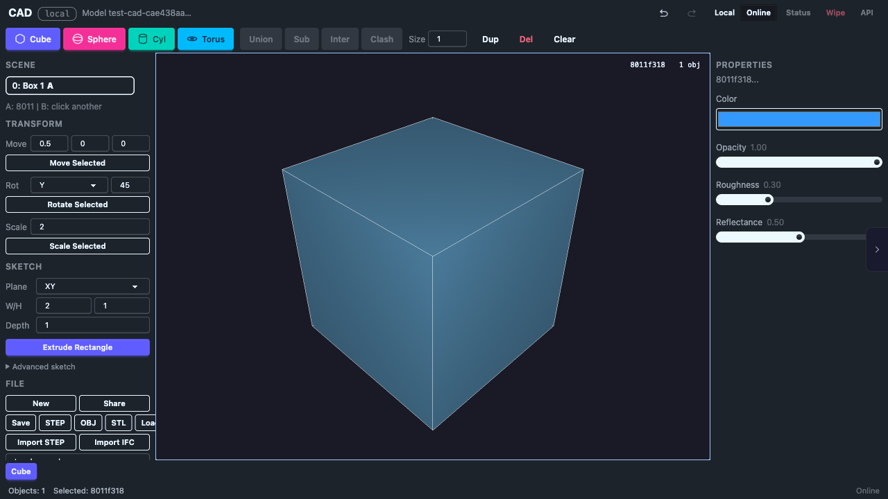
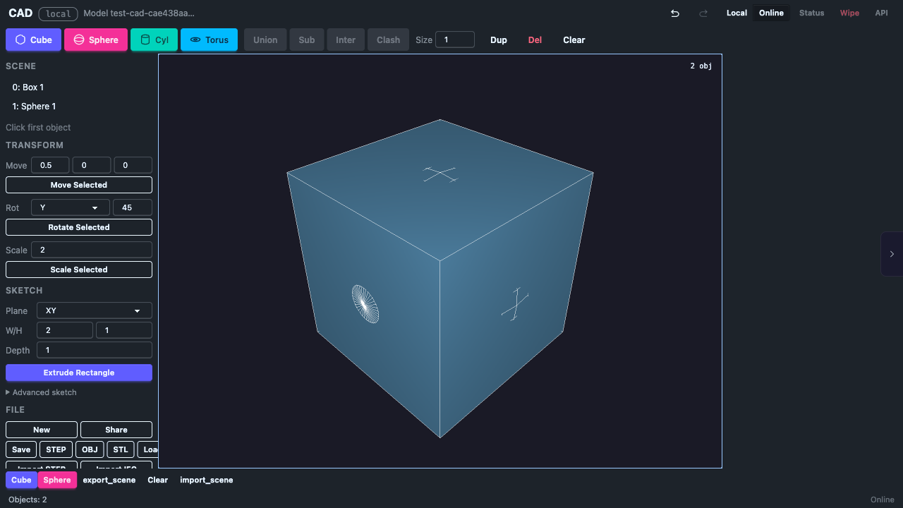
When the app loads you see a default cube in a 3D viewport. The cube is automatically selected (highlighted with a gizmo).
## Camera Controls
| Input | Action |
|---|---|
| Left drag | Rotate camera |
| Scroll / pinch | Zoom in/out |
| Right-click drag | Move light source |
| Touch (1 finger) | Rotate camera |
| Touch (2 finger pinch) | Zoom in/out |
## Gizmo Controls
| Input | Action |
|---|---|
| Click object | Select it (shows translate gizmo) |
| Drag gizmo arrow | Move object along that axis |
| Escape | Cancel drag (reverts to original position) |
| Delete | Delete selected object |
| Click empty space | Deselect |
## Keyboard Shortcuts
| Key | Action |
|---|---|
| Ctrl+Z | Undo |
| Ctrl+Shift+Z | Redo |
| Escape | Cancel drag, deselect, or cancel active sketch |
| Delete | Delete selected object |
| S | Switch to Sketch tab |
## UI Overview
## Requirements
- Chrome 113+ or any browser with WebGPU support
- Desktop or tablet (mobile works with touch controls)
# Known Issues
## Current Limitations
- **Sphere/Torus booleans fail** — Boolean operations only work reliably with cubes and cylinders. Sphere and torus booleans crash due to NURBS surface intersection limitations in the upstream truck-shapeops library.
- **Object size changes after translate** — Moving an object may slightly change its rendered size due to bounding box renormalization. This is a rendering artifact; the B-Rep geometry is unchanged.
- **Large translations go off screen** — The camera doesn't follow translated objects. Keep dx/dy/dz values small (0.1 to 5.0) to stay in view.
- **No rotate/scale gizmo** — Only translate gizmo is currently supported. Rotate and scale transforms are planned.
- **Bounding sphere picking** — Object selection uses bounding sphere approximation, which may be imprecise for elongated or flat objects. Mesh-level raycasting is planned.
## Sketch Limitations
- **No arc/circle sketch entities** — Only straight edges (line segments) are supported. Arcs and circles are planned.
- **No sketch overlay** — Sketch geometry is not visually rendered on the canvas. Use the Solve button to preview solved positions in the status bar.
- **Closed loop required** — Extrude requires edges to form a single closed polygon. Branching or open edge graphs will fail.
- **No face-based sketch planes** — Sketch planes are limited to XY, XZ, YZ. Sketching on a face of an existing solid is planned.
## Fixed in v0.2
These issues from v0.1 have been resolved:
- ~~No click-to-select~~ — Objects can now be selected by clicking in the viewport
- ~~No undo~~ — Full undo/redo with Ctrl+Z / Ctrl+Shift+Z
- ~~Objects selected by index only~~ — Gizmo-based direct manipulation now available
## Fixed in v0.3
- ~~No parametric modeling~~ — Full sketch → constrain → extrude workflow now available
- ~~No constraint solver~~ — ezpz integrated with 11 constraint types
# Boolean Operations
Combine overlapping objects using CSG (Constructive Solid Geometry).
## Operations
| Operation | Description |
|---|---|
| **Union** | Merge A and B into one solid |
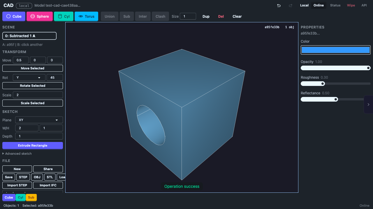
| **Subtract** | Cut B out of A |
| **Intersect** | Keep only the overlapping region |
## How to Use
1. Click an object to select it as **A**, then Shift+click a second object for **B**
2. Click the operation button (Union, Subtract, or Intersect)
3. The two input objects are replaced with the result
The result gets a new UUID. Both input objects are removed from the scene.
## Requirements
- Objects **must overlap** for boolean operations to work
- Objects must be valid B-Rep solids
## Known Limitations
- Boolean operations work reliably with cubes and cylinders
- Sphere and torus booleans may fail due to NURBS surface intersection limitations in the upstream truck-shapeops library
- All boolean operations are recorded in the undo history
## Undo
Boolean operations can be undone with **Ctrl+Z**. Undo restores both original objects to their pre-operation state.
# Save and Load
## Save JSON
Click **Save JSON** to download the current scene as a `.json` file. The file contains full B-Rep data for every object, including:
- Object UUIDs
- Complete solid geometry (no tessellation loss)
- Exact mathematical surface definitions
## Load JSON
Click **Load JSON** to restore a previously saved scene. This replaces the current scene with the loaded one.
## File Format
The JSON format stores an array of objects, each with:
```json
[
{
"id": "550e8400-e29b-41d4-a716-446655440000",
"solid": { ... }
}
]
```
The `solid` field contains the truck B-Rep serialization — vertices, edges, faces, and surface definitions.
## Example Scenes
The **Load example** dropdown provides pre-built scenes:
- Default cube
- Two overlapping cubes
- Multi-primitive scene
- Boolean subtract result
- Complex assembly
## Automerge Documents
Beyond JSON save/load, scenes are also persisted via Automerge documents:
- **New Doc** — creates a fresh Automerge document
- **Share** — copies the document URL for collaborative editing
- Documents sync across tabs via BroadcastChannel
- Each document has a unique `automerge:` URL
# Scene Management
## Object List
The Scene section shows all objects in the current scene. Each object is displayed as `[index:uuid-prefix]`. The selected object is marked with `*`.

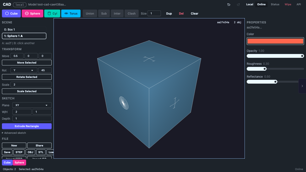
## Selection
- **Click an object** in the viewport to select it
- **Click empty space** to deselect
- Selected objects show a translate gizmo (3 colored arrows)
## Delete
- **Delete Sel.** — removes the currently selected object
- **Delete key** — keyboard shortcut for the same action
- Deletion can be undone with Ctrl+Z
## Clear All
Removes all objects from the scene. This creates a blank scene.
## Undo / Redo
| Action | Shortcut |
|---|---|
| Undo | Ctrl+Z |
| Redo | Ctrl+Shift+Z |
The undo system uses snapshots for fast restoration. Related operations (like adding a primitive and offsetting it) are grouped into single undo steps.
### Timeline
The timeline strip shows recent operations as chips. Each chip represents an undoable action (add, translate, boolean, delete, clear).
## Collaborative Editing
When multiple browser tabs are open, changes sync automatically via BroadcastChannel. Each tab sees the same scene state.
# Creating Shapes
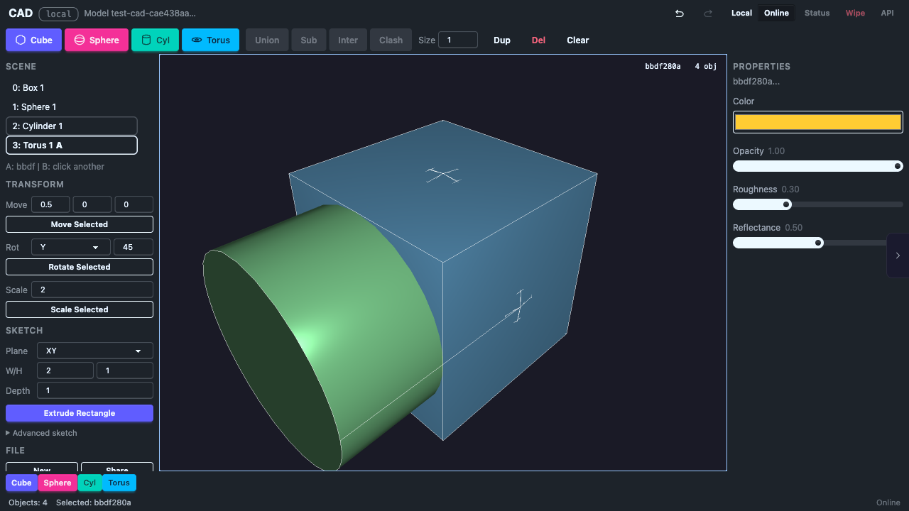
## Primitives
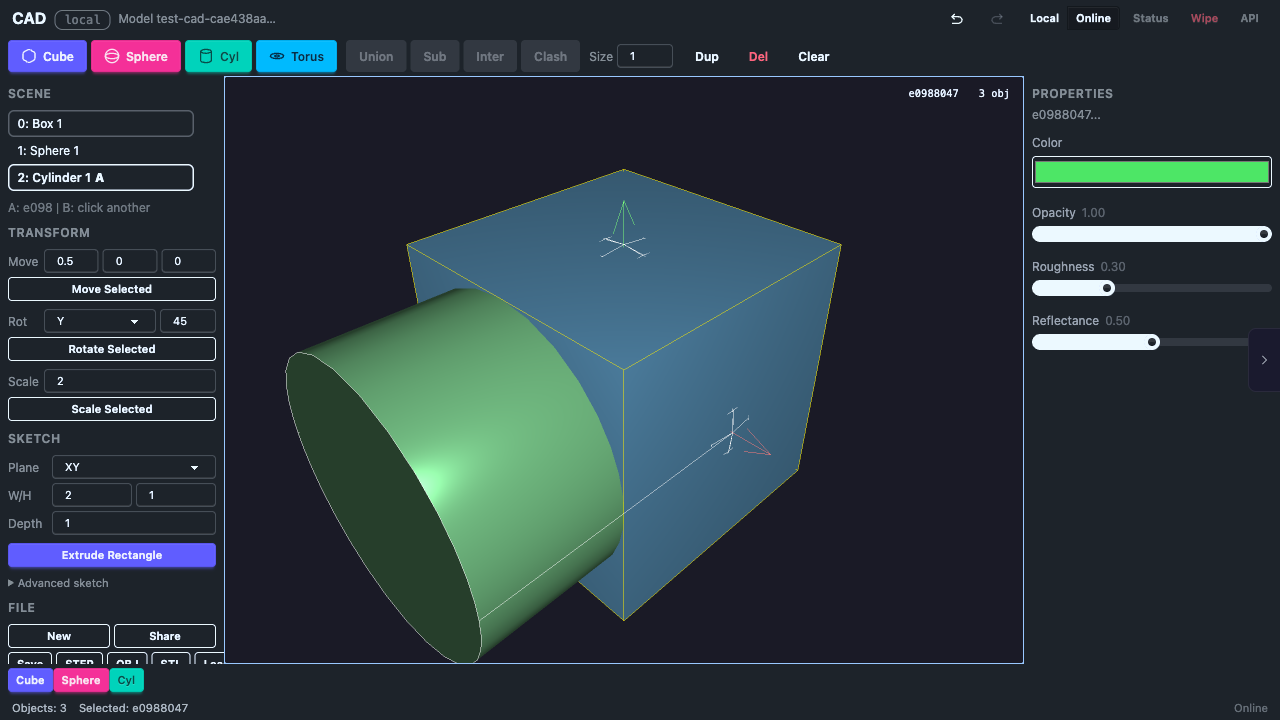
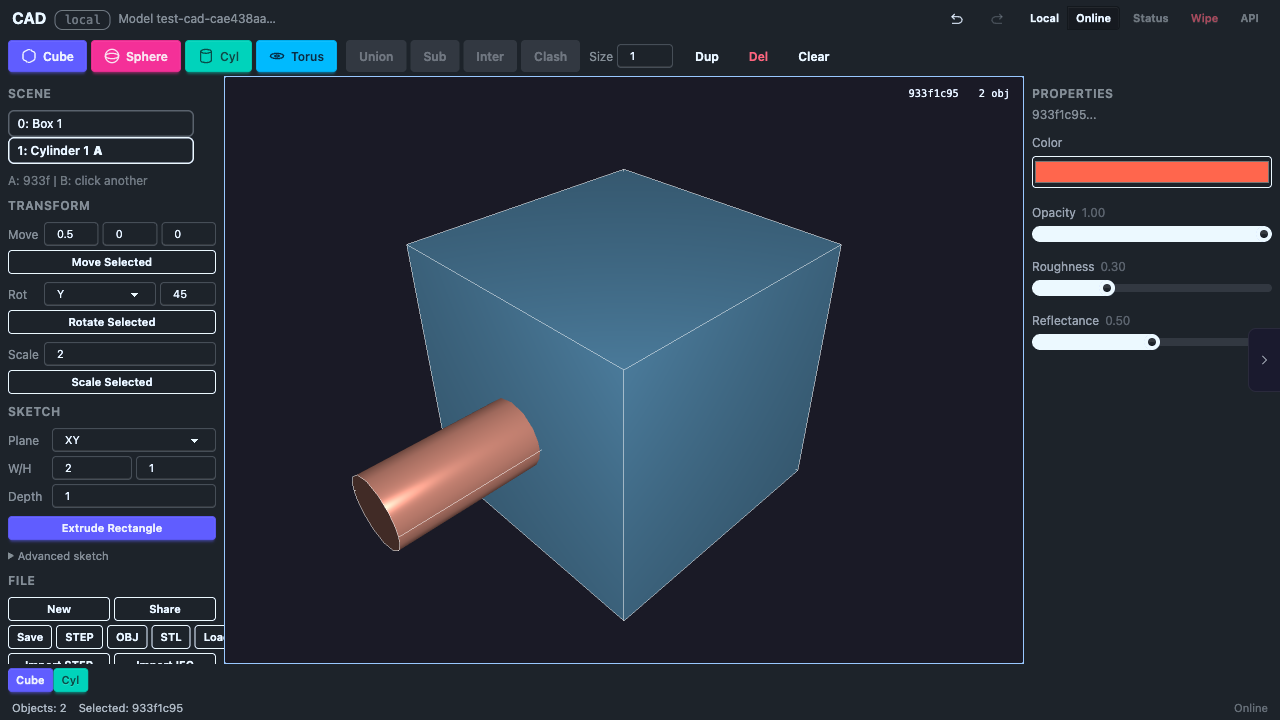
Set the **Size** parameter, then click a shape button. Each new shape is automatically offset so objects partially overlap — ready for boolean operations.
| Shape | Description |
|---|---|
| **Cube** | Box with the given edge length |
| **Sphere** | Sphere with the given radius |
| **Cylinder** | Radius = size/2, height = size |
| **Torus** | Major radius = size, tube radius = size x 0.3 |
## How It Works
Each primitive is created as a full B-Rep (Boundary Representation) solid using the truck CAD kernel compiled to WASM. This means:
- Exact mathematical surfaces (not mesh approximations)
- Boolean operations work correctly
- Export preserves full precision
- Each object gets a UUID for stable identity
## Size Parameter
The size input (default: 1.0, minimum: 0.1) controls the scale of new primitives. Adjust it before clicking a shape button.
## Auto-Offset
New shapes are automatically placed with a small offset from existing objects. This ensures they overlap, which is required for boolean operations to work.
# Moving Objects
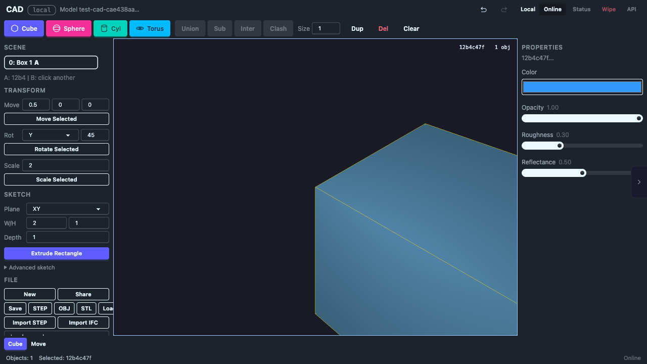
## Gizmo Drag (Direct Manipulation)
Click an object to select it. Three colored arrows appear at its center:
- **Red arrow** (X axis) — drag to move left/right
- **Green arrow** (Y axis) — drag to move up/down
- **Blue arrow** (Z axis) — drag to move forward/back
Drag an arrow to move the object along that axis. The movement is constrained to a single axis for precision.
### Cancel a Drag
Press **Escape** while dragging to cancel. The object snaps back to its position before the drag started.
### Commit
When you release the mouse button, the translation is committed to the undo history. You can undo it with **Ctrl+Z**.
## Panel Transform
You can also enter exact translation values in the Transform section of the tool panel:
1. Enter dx, dy, dz values
2. Click **Move Selected**
The object moves relative to its current position.
## Camera During Drag
Camera rotation is automatically disabled while dragging a gizmo arrow, so you can drag precisely without accidentally rotating the view.